
Cooling Tower Sizing: Step-by-Step Calculation With a Worked Example
Cooling tower sizing starts with four numbers: water flow, hot water temperature, cold water temperature, and the local wet-bulb temperature. For a 30 m³/h tower cooling water from 42 °C to 32 °C at a 28 °C wet bulb, the heat load is about 348 kW. That calls for roughly 38,500 m³/h of air, a plan area of 2 to 3 m², and an estimated fan shaft power of about 2.7 kW.
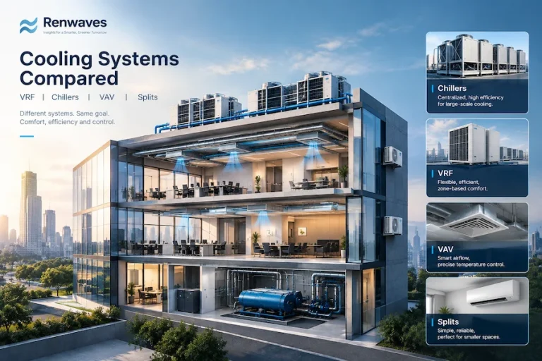
Below is the full calculation, one step at a time. It is a preliminary method, good for checking a quote or planning a project. If you are still deciding which cooling system to use, start with our cooling systems comparison.
⭐ Highlights
- Start with local wet-bulb conditions. Use design wet-bulb temperature to assess cooling potential.
- Pay attention to the approach. Smaller approaches usually require larger, costlier towers.
- Treat quick sizing values as estimates. Check airflow, fill area, and fan selection against manufacturer data.
- Size the pump for the whole system. Include static lift, nozzle pressure, and system friction losses.
What Is a Cooling Tower and How Does It Work?
📘 Definition
A cooling tower is a heat rejection device that cools water by evaporating a small part of it into moving air.
Hot water is sprayed over a fill (also called packing) while air moves through it. A little water evaporates and carries the heat away, and the rest drops into the basin colder than it came in.
In an induced draft tower, the fan sits on top and pulls air up through the fill. Drift eliminators catch droplets before the air leaves.
Design Inputs for the Example
We will size an induced draft tower for the conditions below. The wet-bulb temperature matters most, because it limits how cold the water can get.
📘 Definition
Wet-bulb temperature is the lowest temperature air can reach by evaporating water into it. It sets the coldest water a tower can deliver.
| Parameter | Value |
|---|---|
| Water flow | 30 m³/h |
| Hot water in | 42 °C |
| Cold water out | 32 °C |
| Wet bulb | 28 °C |
| Range | 10 °C |
| Approach | 4 °C |
Step 1: Calculate the Heat Load
Cooling tower sizing begins with the heat load, the energy the tower must remove from the water. Use the following relationship:
📐 Formula
Q̇ = ṁ_water × c_p × ΔT
- Mass flow: 1,000 kg/m³ × 30 m³/h = 30,000 kg/h
- Specific heat of water: 4.18 kJ/(kg·°C)
- Heat load: 30,000 × 4.18 × (42 − 32) = 1,254,000 kJ/h
- Divide by 3,600 to get kW: about 348 kW
Step 2: Check Range and Approach
📘 Definition
Approach is the gap between the cold water temperature and the wet-bulb temperature.
Range is the temperature drop across the tower. Approach is the difference between cold-water temperature and entering-air wet-bulb temperature. A smaller approach means more fill area and a pricier tower. Manufacturers rarely guarantee an approach below about 3 °C (5 °F), according to Marley’s cooling tower basics guide, so 4 °C is reasonable but tight.
📐 Formula
Range = T_hot − T_cold
Approach = T_cold − T_wb
Step 3: Estimate the Air Flow
For a preliminary estimate, we can assume an air-to-water mass ratio. This is a simplifying assumption, not a universal cooling-tower design rule. Final airflow must be checked using the entering and leaving air conditions, a psychrometric heat-and-mass balance, and the manufacturer’s performance data. For this kind of duty, a ratio between 1.0 and 2.0 kg of air per kg of water is common. We adopt 1.5.
📐 Formula
V̇_air = (r × ṁ_water) ÷ ρ_air
- Air mass flow: 1.5 × 30,000 = 45,000 kg/h
- Air density at 28 °C and 1 atm: about 1.17 kg/m³
- Air volume: 45,000 ÷ 1.17 = about 38,500 m³/h
Quick sanity check: each kilogram of air must absorb about 28 kJ (1,254,000 ÷ 45,000). That is realistic for these conditions.
Step 4: Find the Plan Area
The simplest check is water loading, which is the water flow per square meter of fill plan area. Typical values depend on fill type and approach.
📐 Formula
A_plan = V̇_water ÷ L_water
| Parameter | Typical range |
|---|---|
| Air-to-water ratio | 1.0-2.0 |
| Water loading | 10-15 m³/h·m² |
| Fan pressure | 100-250 Pa |
| Fan efficiency | 0.5-0.7 |
At 10 to 15 m³/h per m², a 30 m³/h flow needs between 2 m² (30 ÷ 15) and 3 m² (30 ÷ 10). Because the 4 °C approach is tight, lean toward the larger area.
⚠️ Caution
This plan area is a screening value. Confirm it against the manufacturer’s rating at your design conditions.
Step 5: Estimate the Fan Power
Estimate fan shaft power from the airflow, total fan pressure, and fan efficiency. With airflow in m³/h and pressure in Pa, use:
📐 Formula
P_fan = (V̇_air × ΔP) ÷ (3,600 × η_fan)
We adopt 150 Pa and a fan efficiency of 0.60.
- P = 38,500 × 150 ÷ (3,600 × 0.60)
- P = about 2.7 kW
- Across the 100 to 250 Pa range: roughly 1.8 to 4.5 kW
The 2.7 kW result is estimated fan shaft power, not electrical input. Select the motor only after accounting for fan-drive and motor efficiencies, service factor, and the manufacturer’s rated duty; a nominal 3 kW motor should not be assumed adequate from this estimate alone.
⚠️ Caution
Do not use fan pressures from ducted air handlers. They are several times higher and will overstate fan power.
Step 6: Estimate the Pump Head and Power
Calculate the pump’s total dynamic head from the actual system: static lift, required pressure at the water-distribution nozzles, and friction losses in pipes, fittings, valves, and equipment. For this example, assume 8 m of total dynamic head and a pump efficiency of 0.65. Use Q in m³/s in the power equation. These are illustrative assumptions; verify them against the actual piping layout and nozzle requirements.
📐 Formula
P_pump = (ρ × g × Q × H) ÷ η_pump
- P = ρ × g × Q × H ÷ η
- P = 1,000 × 9.81 × (30 ÷ 3,600) × 8 ÷ 0.65
- P = about 1.0 kW of pump shaft power
Step 7: Calculate Water Loss and Makeup
Evaporation removes the heat, so it also consumes water. Divide the heat load by the latent heat of vaporization, about 2,400 kJ/kg.
📐 Formula
ṁ_evap = Q̇ ÷ h_fg
B = E ÷ (CoC − 1)
M = E + B (drift ignored)
- Evaporation: 348 kW ÷ 2,400 kJ/kg = 0.145 kg/s, or about 0.52 m³/h (1.7% of flow)
- Blowdown at 4 cycles of concentration: 0.52 ÷ (4 − 1) = about 0.17 m³/h
- Makeup water: 0.52 + 0.17 = about 0.70 m³/h, ignoring drift
⚠️ Caution
Cooling towers need water treatment and regular cleaning. Poor control can lead to scale and Legionella growth.
Cooling Tower Sizing Results at a Glance
| Item | Result |
|---|---|
| Heat load | 348 kW |
| Air flow | 38,500 m³/h |
| Plan area | 2-3 m² |
| Fan shaft power | 2.7 kW |
| Pump shaft power | 1.0 kW |
| Evaporation | 0.52 m³/h |
| Makeup water | 0.70 m³/h |
In this cooling tower sizing example, the estimated fan and pump shaft powers total about 3.7 kW to reject 348 kW of heat. This is roughly 1.1% of the heat-rejection rate, not the system’s total electrical consumption.
Common Cooling Tower Sizing Mistakes
- Using dry-bulb instead of wet-bulb temperature
- Ignoring the approach, which drives tower size more than the range does
- Counting only piping losses when sizing the pump
- Forgetting makeup water and blowdown
- Designing for average weather instead of the hottest wet-bulb conditions
When to Bring In an Engineer
A hand calculation gets you to the right size range. Final selection also needs manufacturer curves, site wet-bulb data, water treatment, noise limits, and a safety margin. Our team handles this kind of work as part of building energy simulation and efficiency consulting. You can see everything we offer on our services page.
Cooling Tower Sizing FAQs
How do you size a cooling tower?
Find the heat load from flow and temperatures, check range and approach, then estimate air flow, plan area and fan power.
What is the difference between range and approach?
Range is hot water minus cold water. Approach is cold water minus wet-bulb temperature.
Why is wet-bulb temperature used instead of dry-bulb?
Evaporation limits cooling, and wet-bulb temperature shows that limit. Cold water cannot go below it.
How much water does a cooling tower use?
The 30 m³/h example needs about 0.70 m³/h of makeup water, roughly 2.3% of the flow.
How much power does a cooling tower fan need?
The example fan needs about 2.7 kW, under 1% of the 348 kW of heat rejected.
Sources and Further Reading
- SPX Marley. Cooling Tower Basics, for range, approach and evaporation fundamentals.
- ASHRAE. Standards and guidelines for HVAC system design.
Typical values for water loading, fan pressure and efficiency vary by tower design. This is an educational guide, not a substitute for a project-specific design.

I’m an engineer specializing in renewable energy technologies, with a master’s degree in mechanical engineering and research focused on thermo-photovoltaic systems. I’ve contributed to ISI journals, presented at international conferences, and written for industry publications, sharing insights on sustainable energy solutions.